
When the fully automatic capacitance bridge tester measures the capacitance value of a capacitor, the test voltage is simultaneously applied to the standard capacitor and the capacitor under test. The processor collects the current signals flowing through both via sensors and processes them to obtain the capacitance value of the capacitor under test.
Fully Automatic Capacitance Bridge Tester;
Fully Automatic Capacitance Bridge Tester
Product Introduction;
This capacitance and inductance tester adopts a bridge circuit structure, with the standard capacitor and the capacitor under test serving as two arms of the bridge circuit. When measuring the capacitance value of a capacitor, the test voltage is simultaneously applied to the standard capacitor and the capacitor under test. The processor collects the current signals flowing through both via sensors and processes them to obtain the capacitance value of the capacitor under test.
Product Features;
(1) Measurement of single-phase capacitors:
For single-phase capacitor testing, connect one end of the red test lead to Ua and the other end with the test clip to one busbar; connect one end of the black test lead to Uo and the other end to another busbar. Connect the output wire of the clamp CT to the Ia terminal of the instrument, and clamp the clamp CT onto the capacitor lead-in end of the busbar connected to the red test clip. When connecting, pay attention that the end of the current clamp marked with "P" faces the capacitor direction and is clamped onto the capacitor; otherwise, the measured phase angle will be incorrect.
If there are multiple single-phase capacitors in the capacitor bank to be tested, after testing the first capacitance value, press the return key. Without moving the voltage test leads, directly open the current clamp and clamp it onto the next capacitor, then press the confirm key to test. This greatly improves testing speed, which is the biggest feature of this instrument.
(2) Measurement of three-phase delta-connected capacitors:
This is the wiring method for measuring three-phase delta-connected capacitors. Connect the measurement leads from the instrument's measurement output terminals according to the corresponding colors. Clamp the yellow clip onto phase A of the busbar, the green clip onto phase B of the busbar, and the red clip onto phase C of the busbar. Then insert the three current measurement leads into the Ia, Ib, and Ic terminals of the instrument respectively and tighten them. Correspondingly, clamp the clamp sensors onto the lead-in wires of phase A, B, and C of the high-voltage capacitor bank. Pay attention to whether the direction of each clamp-type current transformer is correct; otherwise, it will cause errors in the phase angle of the measured capacitance.
(3) Measurement of three-phase Y-connected capacitors:
The wiring method for three-phase Y-connected capacitors is the same as that for delta-connected capacitors, except that during measurement, select the three-phase Y-connected capacitor measurement. No specific introduction will be provided here.
(4) Measurement of three-phase Yn-connected capacitors:
Figure 6 shows the wiring method for measuring three-phase Yn-connected capacitors. Connect the measurement leads from the instrument's measurement output terminals according to the corresponding colors. Clamp the yellow clip onto phase A of the busbar, the green clip onto phase B of the busbar, the red clip onto phase C of the busbar, and the black clip onto the N busbar. Then insert the three current measurement leads into the Ia, Ib, and Ic terminals of the instrument respectively and tighten them. Correspondingly, clamp the clamp sensors onto the lead-in wires of phase A, B, and C of the high-voltage capacitor bank. Pay attention to whether the direction of each clamp-type current transformer is correct; otherwise, it will cause errors in the phase angle of the measured capacitance.
Fully Automatic Capacitance Bridge Tester
Product Parameters;
(1) Capacitance measurement range: 0.1μF to 3,300μF
(2) Reactive power measurement range: 5 to 20,000 kvar
(3) Measurement accuracy: ±(1.0% reading + 0.02μF)
(4) Resolution: 0.001μF
Current Measurement
(1) Current measurement range: 0 to 20A
(2) Measurement accuracy: ±(3.0% reading + 0.05A)
(3) Resolution: 0.01A
c. Inductance Measurement
(1) Inductance measurement range: small inductance mode 200μH to 5mH
large inductance mode 5mH to 10H
(2) Inductive reactance measurement range: 100mΩ to 20KΩ
(3) Measurement accuracy: ±(3.0% reading + 0.05mH)
(4) Resolution: 0.01mH
d. Resistance measurement range:
(1) Resistance measurement range: small resistance mode 50mΩ to 1Ω
large resistance mode 1Ω to 20KΩ
(2) Measurement accuracy: ±(3.0% reading + 0.05Ω)
(3) Resolution: 0.01Ω 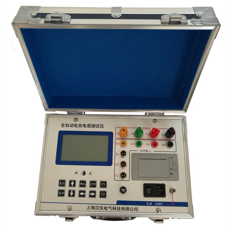
Article Guide:
In the eyes of the boss: at work, not only should we value the process, but also implement tasks; only by achieving results can employees demonstrate their abilities.
Discussion
1. How do you view the "work process" and "work results"?
2. Talk about the relationship between results and personal abilities.