Automatic Capacitance Bridge Tester Manufacturer
Darui Electric recommends:
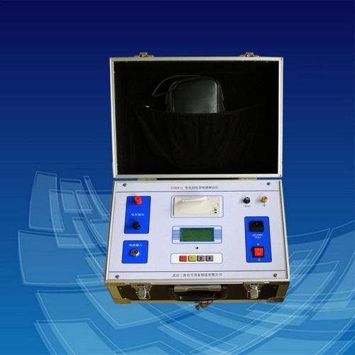
Introduction to Automatic Capacitance Bridge Tester
It mainly solves the following problems:
(1) On-site measurement of capacitors requires removing connecting wires, which is not only labor-intensive but also prone to damaging capacitors;
(2) The low output voltage of capacitance meters leads to a low fault detection rate.
This instrument features small measurement workload, quick and simple operation, stable performance, accurate measurement, and high fault detection rate. In addition, its current measurement unit can also be used for measuring electrical equipment such as CVTs and arresters, offering multi-functionality in one device.
Features of the Automatic Capacitance Bridge Tester:
Automatic range conversion
Data storage
Large-screen LCD (320×240×LCD) display with Chinese menu operation prompts.
Simultaneous display of waveform and measurement data on the same screen, making the testing process more intuitive;
Equipped with setting, calibration, and debugging functions
Technical Parameters
1. Measurement range and accuracy of the instrument:
a. Capacitance measurement
(1) Capacitance measurement range: 0.1μF to 2,000μF;
(2) Reactive power measurement range: 5 to 20,000 kvar;
(3) Measurement accuracy: ±1.0%;
(4) Resolution: 0 to 1.999μF ±1.0%rdg;
0 to 19.99μF ±1.0%rdg;
0 to 199.9μF ±1.0%rdg;
0 to 1999μF ±1.0%rdg;
b. Current measurement
(1) Current measurement range: 0 to 199.9mA;
0 to 1.999A;
0 to 19.99A;
0 to 199.9A
0 to 1000A;
(2) Measurement accuracy: ±1.0%;
2. Power supply:
a. Rated voltage: 220V±10% AC;
b. Rated frequency: 50Hz;
c. Rated output: 26V/500VA;
3. Normal working conditions of the instrument:
a. Ambient temperature: 0℃ to +40℃
b. Relative humidity: ≤90%
4. Display mode: Large-screen LCD with full Chinese output,
TPμp-40 panel-mount thermal printer
5. Dimensions/Weight: 320×360×160 mm / 8 kg
6. Working principle
The capacitance bridge adopts a bridge circuit structure, with the standard capacitor and the tested capacitor as two arms of the bridge. When measuring the capacitance value, close the test switch K, and the test voltage is applied to both the standard capacitor and the tested capacitor simultaneously. The processor collects the current signals flowing through both via sensors and processes them to obtain the capacitance value of the tested capacitor.
Due to the synchronous sampling technology of the standard capacitor and the tested capacitor, it is immune to power supply voltage fluctuations; moreover, the measurement process is fully automatic, avoiding errors caused by manual operation, thus featuring good stability, repeatability, accuracy, and reliability.
Note: The above information and technical parameters are compiled and released by Yangzhou Darui Electric Co., Ltd.