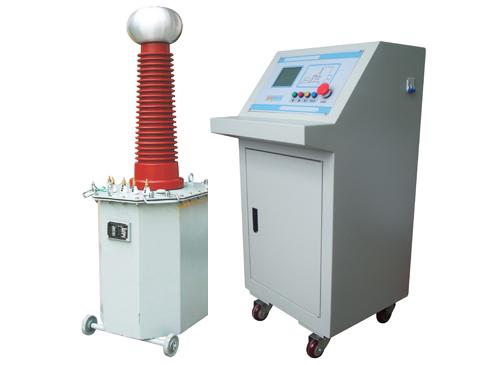
GYSB AC Series Excitation Test Transformer
Darui Electric recommends for you:
Product Detailed Introduction
The GYSB series AC Series Excitation Test Transformer is a new type of high-voltage testing equipment. This series of products AC Series Excitation Test Transformer adopts a single-frame core-type iron core structure, with the primary winding and high-voltage winding coaxially wound on the iron core, thereby reducing leakage flux and increasing coupling between windings. The overall structure of the product is compact, with strong universality, easy to use and carry, suitable for power systems and power users to test the insulation performance of various high-voltage electrical equipment on site. The AC Series Excitation Test Transformer is an essential test instrument for power equipment testing and preventive tests.
1. AC Series Excitation Test Transformer Product Overview
The GYSB series AC Series Excitation Test Transformer is a new type of high-voltage testing equipment. This series of products adopts a single-frame core-type iron core structure, with the primary winding and high-voltage winding coaxially wound on the iron core, thereby reducing leakage flux and increasing coupling between windings. The overall structure of the product is compact, with strong universality, easy to use and carry, suitable for power systems and power users to test the insulation performance of various high-voltage electrical equipment on site. It is an essential test instrument for power equipment testing and preventive tests.
In addition to being used for AC power frequency withstand voltage tests, the GYSB series AC Series Excitation Test Transformer can also be assembled into a DC high-voltage test device when equipped with capacitors, silicon stacks, and high-voltage DC microammeters of the same voltage level and capacity, allowing measurement of high-voltage DC leakage current.
GYSB AC Series Excitation Test Transformer
2. AC Series Excitation Test Transformer Operation Steps
1. Connect the leads according to the wiring schematic diagram, and reliably ground the transformer and control box;
2. Before the test, check whether the wiring at each part is in good contact, and check whether the voltage regulator of the control box is adjusted to the "zero" position;
3. Connect the power supply, the green indicator light turns on, press the start button, the red indicator light turns on, indicating that the transformer is energized, waiting for voltage increase;
4. Rotate the voltage regulator handle clockwise at a uniform speed to increase the voltage, and closely pay attention to the instrument readings and the condition of the test object;
5. After the test is completed, quickly reduce the voltage to zero, press the stop button, then cut off the power supply, and disconnect the test leads.
3. AC Series Excitation Test Transformer Precautions
1. When conducting high-voltage tests, at least 2 or more personnel must participate, with clear division of labor and clear mutual methods. There must be a dedicated person to supervise on-site safety and observe the test status of the test object;
2. The transformer and control box should have reliable grounding;
3. During the test, the voltage increase speed should not be too fast, and sudden full voltage energization or de-energization is absolutely not allowed;
4. During the voltage increase or withstand voltage test, if any of the following abnormal conditions are found, immediately reduce the voltage, cut off the power supply, stop the test, and investigate the cause before conducting the test again.
① The voltmeter pointer swings greatly;
② There is an odor of burning insulation or smoke;
③ There are abnormal sounds inside the test object.
5. During the test, if the test object is short-circuited or breaks down, the overcurrent relay in the control box operates. At this time, return the voltage regulator to zero, cut off the power supply, and then the test object can be removed.
6. When conducting capacitance tests or DC high-voltage leakage tests, after the test is completed, reduce the voltage regulator to zero, cut off the power supply, and then use a discharge rod to discharge the high-voltage end of the test object or capacitor to ground to avoid the risk of electric shock from the potential stored in the capacitor.
Note: The above information and technical parameters are compiled and released by Yangzhou Darui Electric Co., Ltd.